
The VSIP showroom regularly welcomes investors, corporate clients, and visiting delegations. During project presentations and investment promotion activities, communicating detailed information about each industrial park is essential. This includes geographical location, master planning, transportation infrastructure, functional amenities, and businesses currently operating within the parks.
Previously, traditional physical scale models were used to illustrate industrial park layouts and spatial configurations. However, as VSIP expanded its operations across multiple locations, this approach revealed several limitations. Each physical model was typically dedicated to a specific area, while updating or adding information about other locations required considerable effort.
VSIP needed a solution that could present multiple industrial parks within a single system while allowing content to be switched flexibly according to the needs of different visitor groups.
To address this requirement, a digital model was selected to replace traditional physical scale models. The system enables 3D models and master planning content for multiple industrial parks to be displayed using pre-developed digital data. In addition, the main display screen provides detailed information about functional amenities, wastewater treatment systems, safety infrastructure, and power supply systems.
For LUXMAGE, the challenge was not simply to install an LED screen as a replacement for a physical model. The system had to meet three key requirements simultaneously: delivering intuitive 3D spatial visualization, enabling flexible content switching, and integrating seamlessly with the showroom architecture and visitor circulation flow.
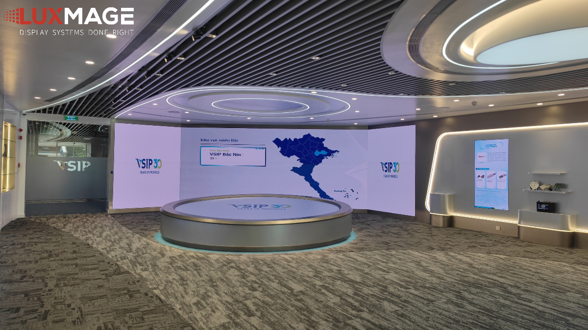
During the initial design phase, the project considered several scale model configurations, including rectangular, square, and circular designs.
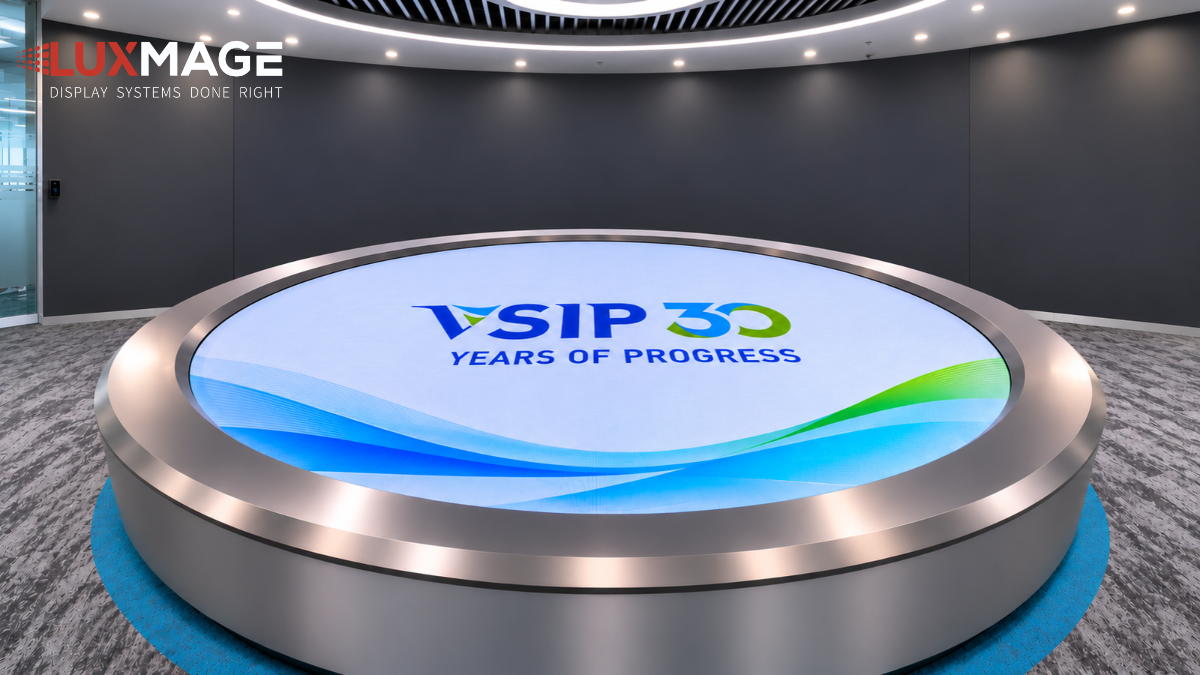
Following multiple discussions and layout simulations, the circular design was selected based on the characteristics of the space and the anticipated movement of visitors. This configuration allows visitors to gather around the model, observe the displayed content from multiple directions, and conveniently follow presentations and discussions.
For a showroom that regularly hosts project presentations and corporate delegations, this arrangement transforms the model into a central presentation area rather than simply another fixed screen mounted on a wall.
Beyond the physical shape, display technology was another key consideration from the beginning. The project adopted COB (Chip-on-Board) display technology with a P1.25 pixel pitch.
Visitors were expected to view the model from a relatively close distance of approximately 1.5 meters. Therefore, the evaluation focused on image sharpness, visual comfort, and glare control during viewing.
With a 1.25 mm pixel pitch, the display provides high pixel density, supporting the presentation of detailed 3D models and master planning content at close viewing distances. COB P1.25 technology was selected following consideration and testing against the project's actual usage requirements.
In this solution, the circular design addresses spatial arrangement and visitor interaction, while COB P1.25 technology meets the image quality requirements for close-range viewing.
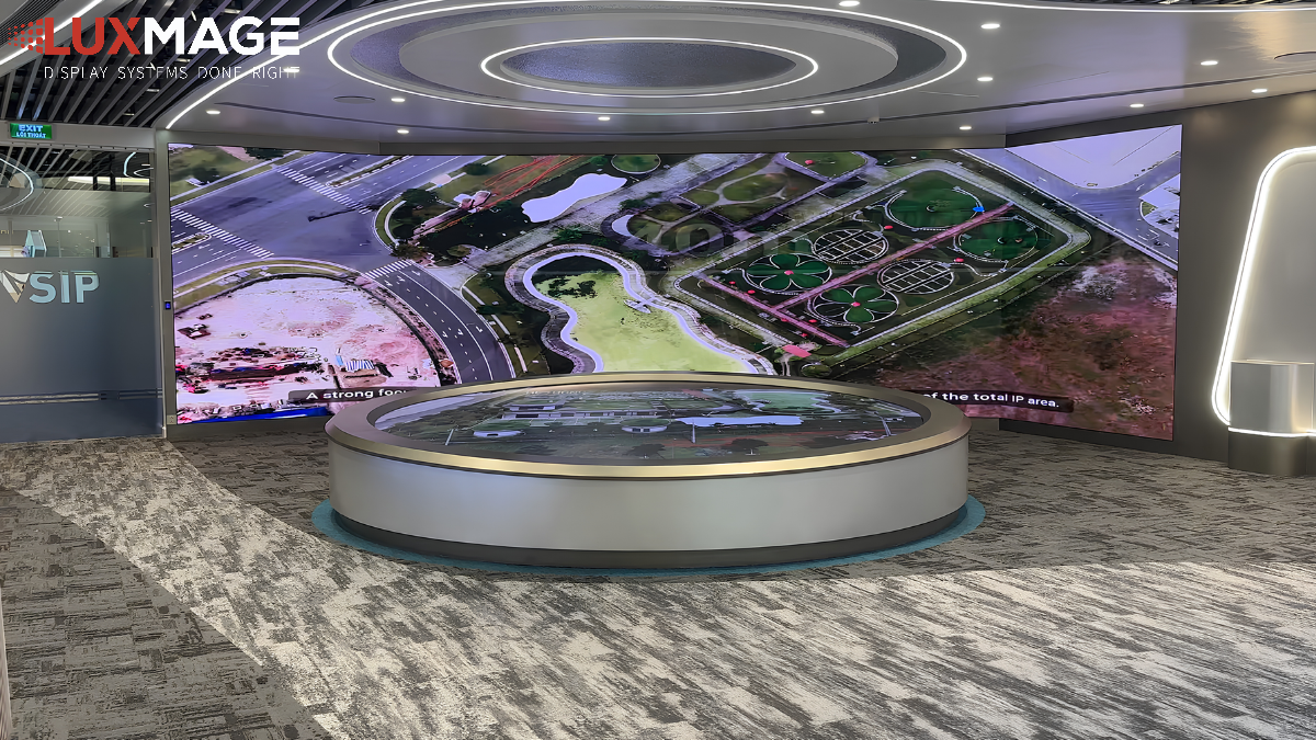
One of the most technically complex aspects of the project was achieving the precise circular profile of the LED scale model.
The initial design used standard COB cabinets measuring 600 × 337.5 mm. However, assembling rectangular cabinets into a circular structure would create stepped edges along the outer perimeter, resulting in an uneven appearance that did not match the intended design.
If an external border were used simply to conceal these uneven edges, its width could exceed 400 mm. This would significantly reduce the effective display area and make the overall structure unnecessarily bulky.
Following discussions with the spatial design team, the project established a requirement to keep the border width below 300 mm. This required the engineering team to redesign the structural solution rather than continue using standard cabinets.
To meet the requirements for shape and display area, LUXMAGE collaborated with manufacturers of aluminum profile frames and PCB boards to research and redesign the cabinet system and its corresponding mainboards.
Reducing the dimensions of the cabinets and display units increased the flexibility of arranging the screen modules along the curved perimeter of the scale model. At the same time, redesigning the mainboard and related components ensured that the customized configuration could be integrated consistently with the overall display system.
This was more than a simple adjustment to cabinet dimensions. The engineering team had to coordinate and validate the compatibility of the cabinets, PCB boards, aluminum profiles, and assembly configuration to ensure that all components met the overall design requirements.
After testing and refinement, the solution achieved the following final specifications:
|
Specification |
Details |
|
Overall outer diameter |
4,106 mm |
|
Actual display area diameter |
3,580 mm |
|
Maximum border width |
≤ 263 mm |
|
Display technology |
LED COB |
|
Pixel pitch |
P1.25 |
Compared with the initial configuration, which could have required a border wider than 400 mm, the customized cabinet design limited the maximum border width to 263 mm while maintaining the required effective display area.
In addition to dimensional optimization, the surrounding border was designed with beveled surfaces on both sides. This treatment reduces the visual impression of thickness and weight, creating a smoother transition between the display surface and the main equipment structure.
For a model positioned at the center of a showroom and viewed from multiple directions, the overall appearance of the structure is also an important factor in maintaining visual harmony with the surrounding space.
This demonstrates how LUXMAGE integrates engineering requirements with architectural design considerations within a single implementation solution.
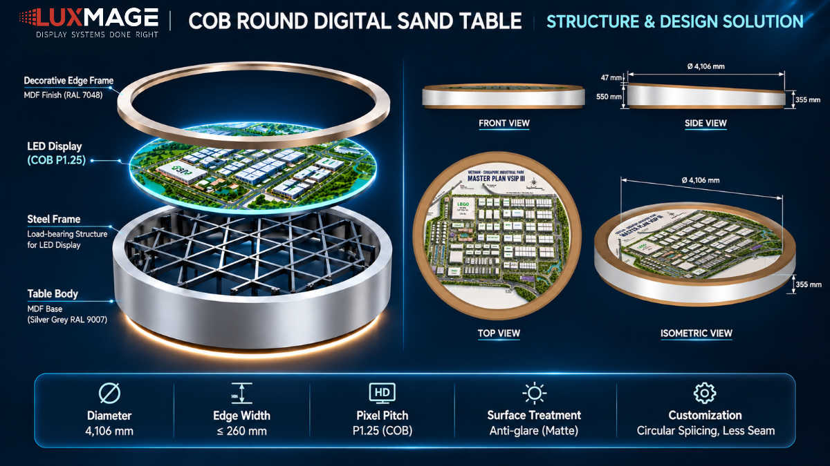
For a large-format LED display with a customized circular structure, accessibility to internal components for inspection or replacement must be considered from the beginning.
At the VSIP project, LUXMAGE incorporated maintenance provisions directly into the structural design process.
Power and signal cables were routed inside the aluminum alloy frame rather than being exposed externally or arranged without a consistent layout.
This approach creates a cleaner overall structure, reduces cable clutter, and makes it easier for technicians to inspect connections during maintenance.
Maintenance access points were arranged around the display assembly, including the top, bottom, left, and right sides. Each access point features a locking mechanism that allows it to be opened and detached when inspection is required.
This enables technicians to access the relevant areas for troubleshooting or component replacement without dismantling the entire frame structure.
By planning these access points during the initial design phase, the system addresses not only appearance and display performance at handover but also inspection and maintenance requirements throughout its operational lifecycle.
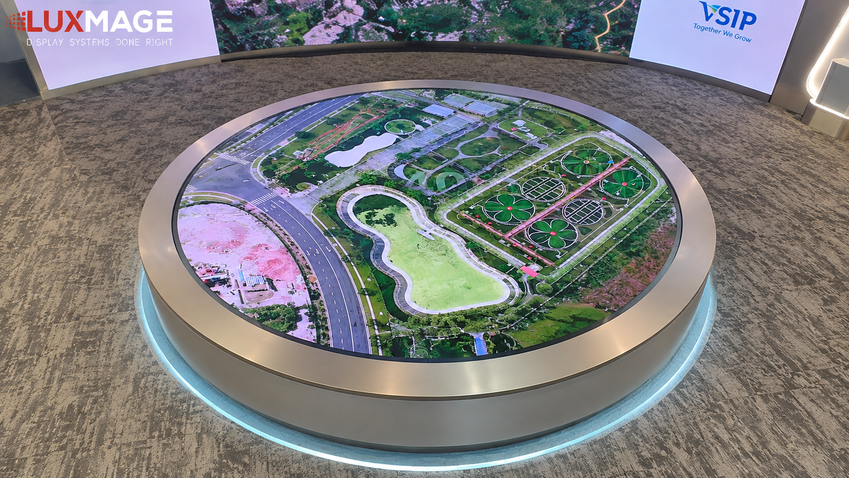
A digital model can only deliver its full value when the displayed content is organized to support the presenter's communication flow.
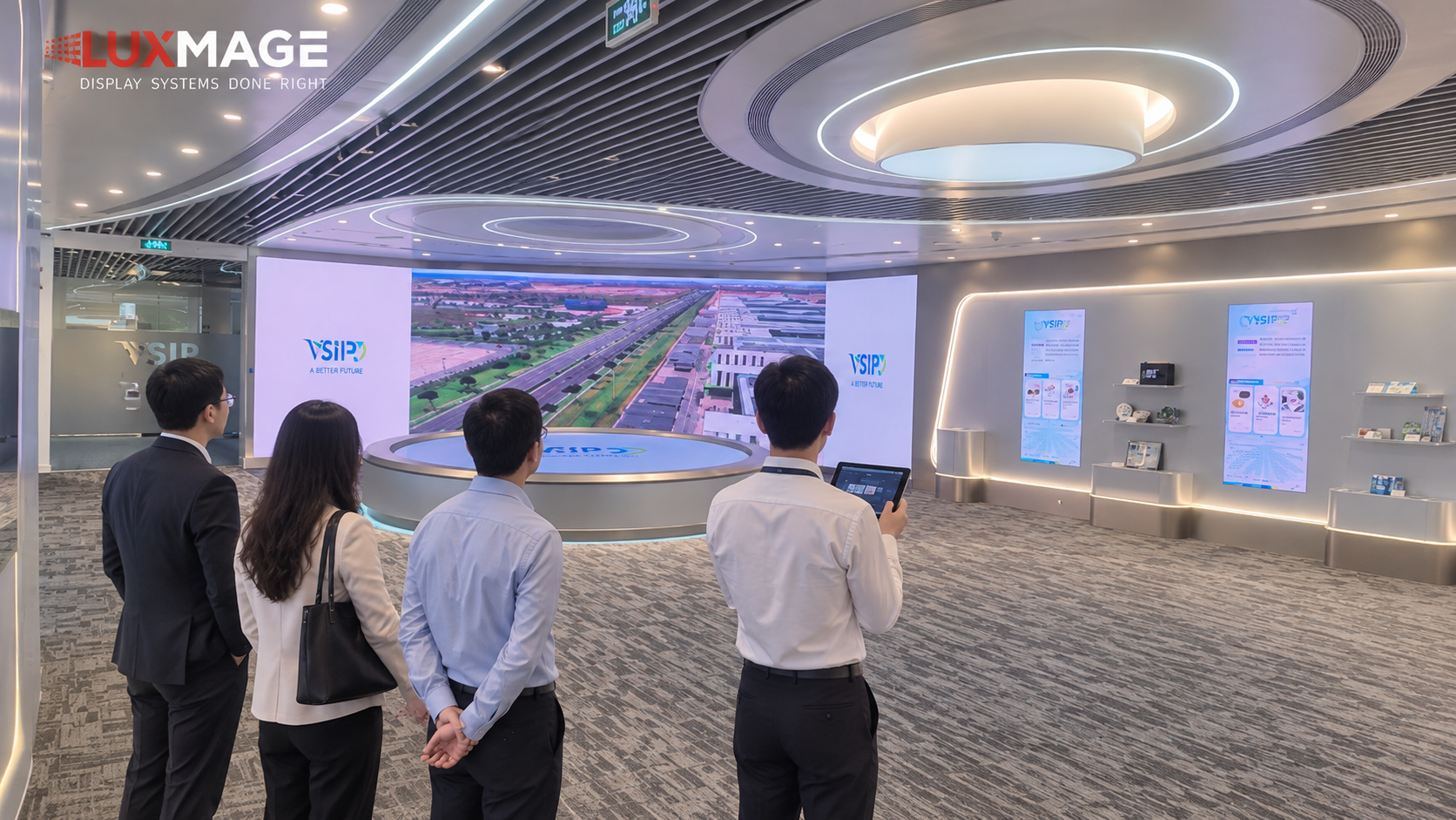
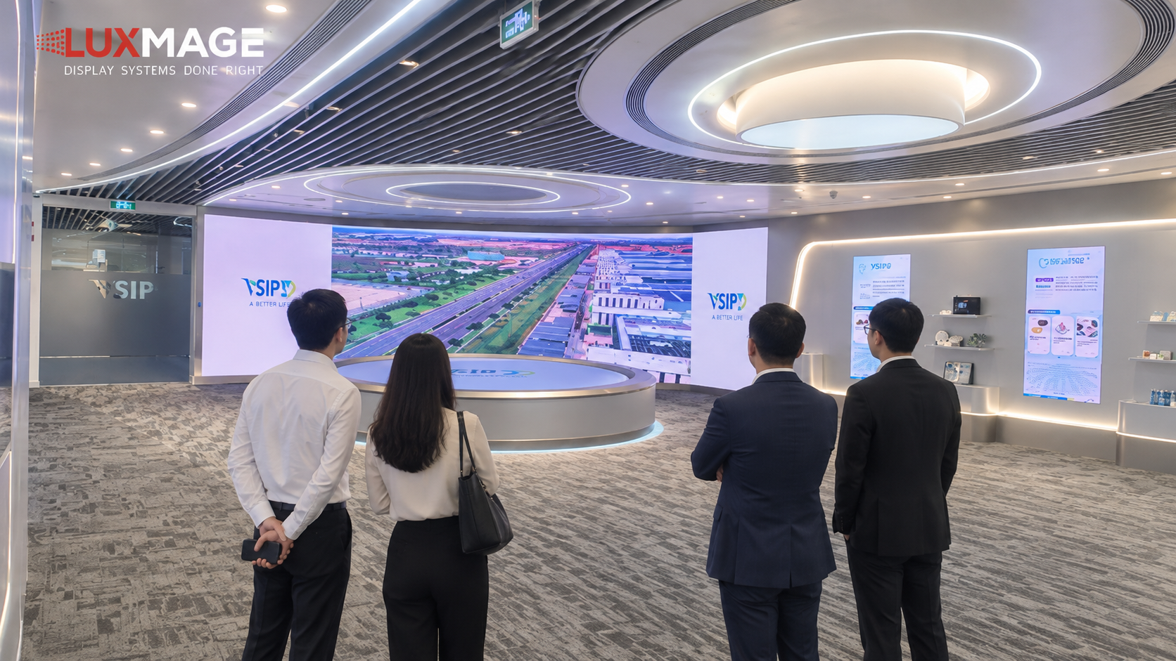
At the VSIP showroom, the LED scale model is integrated with the main display behind it, creating two complementary display areas.
The LED scale model is responsible for presenting 3D models, overall layouts, and spatial relationships between different areas within the industrial parks.
Through these digital models, visitors can more intuitively understand the location, master planning, and spatial organization of each industrial park compared with viewing technical drawings or static images alone.
Approximately 2 meters behind the scale model is the main COB P1.53 LED display, designed in a three-sided configuration consisting of one central screen and two fixed side panels.
Main Display Specifications:
|
Specification |
Details |
|
Display technology |
COB P1.53 LED |
|
Total unfolded width |
9,920 mm |
|
Height |
2,560 mm |
|
Central screen width |
6,080 mm |
|
Width of each side panel |
1,920 mm |
|
Configuration |
Three-sided design: one central screen and two side panels |
The main display presents detailed information about individual industrial parks, including functional amenities and important technical infrastructure such as wastewater treatment systems, safety systems, and power supply systems.
While the digital scale model provides an overall spatial perspective, the main display supplements it with in-depth information, helping visitors better understand the characteristics and infrastructure of each industrial park.
The system is configured for iPad-based control. Presenters can actively select and switch displayed content according to the audience and the progression of each presentation.
For example, when introducing a specific industrial park, the presenter can use the digital scale model to explain its location and overall master plan while simultaneously switching the main display to show relevant infrastructure, amenities, and technical specifications.
This coordinated approach keeps the content on both display areas aligned with the presentation while allowing presenters to adjust the pace according to different client groups.
Visitors can therefore follow a clear information sequence, moving from an overall understanding of the spatial layout to more detailed information about each industrial park.
Beyond technical and aesthetic requirements, the implementation schedule was another significant challenge for the VSIP project. In particular, the LED scale model required custom-designed cabinets and mainboards, involving additional time for engineering research, design confirmation, and validation before production could begin.
From early August, discussions on design options and technical evaluations continued in parallel. The final system configuration was not agreed upon until August 16.
According to the project plan, the customized design and technical confirmation phase was expected to take 20–30 days. This was followed by production, transportation, full screen assembly at the LUXMAGE factory, and system operation testing.
Meanwhile, the client's required handover deadline was October 15. The schedule also had to account for China's National Day holiday in early October, which could affect the supplier's production and transportation activities. Therefore, the shipment needed to be arranged no later than September 25 to allow sufficient time for subsequent stages.
The greatest challenge was coordinating the design schedule, precision of customized components, and the entire production–transportation–assembly–system testing process. In particular, for a product featuring a custom-engineered circular structure, technical confirmation before production was critical, as any changes at a later stage could affect the entire implementation schedule.
The project therefore required close coordination among the design team, engineering team, manufacturers, and logistics partners to ensure that all components were completed in the correct sequence and delivered within the agreed timeframe.
During investor reception sessions, presenters can use an iPad to select the industrial park they wish to introduce. The LED scale model displays its 3D model and overall master plan, while the main screen provides detailed information about power supply systems, wastewater treatment, and functional amenities.
When visitors want to explore another industrial park, presenters can proactively switch to the corresponding content already prepared within the system.
The combination of the digital scale model, main display, and iPad control allows VSIP to introduce multiple industrial parks within a single space while flexibly adjusting the presentation according to the information needs of each visiting delegation.
As a result, presentations can progress from an overall understanding of master planning to more in-depth infrastructure information, supporting VSIP's project introduction and investment promotion activities.
Every LED display project comes with specific requirements related to architecture, dimensions, viewing distance, display content, and operating methods. For systems with specialized configurations, such as a circular digital scale model, selecting the right display equipment is only one part of the implementation process.
What matters is ensuring seamless coordination between display technology, cabinets, circuit boards, mechanical structures, cabling systems, maintenance solutions, and control platforms.
Through the VSIP Digital Showroom project, LUXMAGE demonstrates its ability to coordinate design and implement solutions based on actual customer requirements, from researching design options and customizing components to system integration, installation, and operational testing.
LUXMAGE is ready to discuss display configurations, structural designs, and control solutions tailored to the architectural characteristics and intended applications of your project.
Are you looking for an LED display solution for a showroom, project showcase center, or digital exhibition space?
LUXMAGE is ready to discuss display configurations, structural design, and control systems tailored to the specific characteristics of your space and the intended use of your project.
Our LUXMAGE factory is located in Ho Chi Minh City, Vietnam. We warmly welcome project owners, design consultants, contractors, and partners to visit our facility. You can explore our LED display technology, production processes, and system integration capabilities firsthand, while also discussing how our commercial display solutions can be applied to your specific projects. Please contact LUXMAGE to schedule a factory visit or to discuss the technical requirements of your project.
Get in touch with us at:
Vi Luc Technology Co., Ltd. – LUXMAGE
Address: 63 Lo Lu, Truong Thanh, Thu Duc, Ho Chi Minh City
Hotline: 0988.895.066 - 093.333.5066
Email: sale@luxmage.com


